11 ACCOMMODATION AND WORKING SPACES
11 ACCOMMODATION AND WORKING SPACES
This chapter applies to all fishing vessels (pre-2004 and post-2004)
11.1General .1The provisions within this chapter, except for those referred to in paragraph.2 below,
represent recommendations thatowners may wish to use for guidance, when optionally upgrading their vessels. .2The following provisions, which are safety-related, must be complied with,taking into account
the size of the vessel and range of operation:
a.flooding danger where a toilet is fitted (section 11.6), b.escapes (section 11.7), c.safety ventilation (section 11.8), and d.lighting (section 11.10).
.3Accommodation and working spaces should be kept clear and, as far as possible, protected
from the sea and provide adequate protection for crew against falls on the vessel or from falling overboard.
11.2Living Quarters .1The location, construction and insulation should provide protection against the sea, weather
and excessive heat or cold.
11.3Sleeping Accommodation .1In vessels intended to be at sea regularly for more than 24 hours, a sufficient number of berths
should be provided on board.
11.4Food Preparation .1Means for cooking and for supplying hot water should be provided, together with adequate
space for the preparation and storage of food. Sufficient ventilation should be provided. .2It is extremely important to take appropriate precautions to prevent instances of foodborne
illness at sea, such as hygienic cleaning of hands by food handlers.
11.5Messing Arrangements .1Where space permits, facilities should be provided to permit the crew to rest and eat when
not working.
11.6Toilet Facilities .1Any toilet which discharges through the side of the vessel must be of an approved commercial
marine standard design and quality, with inlet and discharge pipe connections complying with section 2.1.18 above. .2When the rim of the toilet is either below, or less than 300mm above, the deepest waterline
of the vessel, anti-siphon measures must be provided.
11.7Access and Escape Arrangements .1Routes and exits, which can be used as emergency escape routes, must be unobstructed,
easily accessible and lead out as directly as possible to the open deck. .2All accommodation and workspaces must normally be provided with an escape, which may
be through any hatch, door, window or portlight, which must have minimum clear opening of 500mm x 380mm. The adequacy of escapes must be functionally tested. .3Emergency hatches or doors must be capable of easy opening from both the inside and the
outside, without the use of keys or tools. The use of a loose handle, hammer or special device kept in a central position, such as the wheelhouse, will be accepted. Emergency exits must not be fitted with padlocks when the vessel is occupied. .4Where emergency routes pass through other spaces, the doors or hatches serving those
spaces must not be capable of being locked, unless kick panels or other suitable alternative arrangements are provided. In all of these cases, escape routes and exits must be indicated by appropriate permanent signs and be illuminated. See paragraph 11.10.2 below. .5In sleeping accommodation, efficient smoke detectors must be provided, as necessary, to give
early warning of a fire emergency, which could cut off escape from a space. .6Ladders, steps, handgrips and suchlike, necessary for escape, must be fitted.
11.8Ventilation .1Effective means of ventilation must be provided to enclosed spaces, which under normal
operating conditions may be entered by persons on board. This is particularly important in sleeping accommodation. In this context it is considered that the hatch will effectively ventilate fish holds. .2Mechanical ventilation may be required for safety reasons in accommodation spaces, which
are situated completely below the level of the weather deck. As far as practicable, such ventilation arrangements must be designed to provide at least 6 changes of air per hour, when the access openings to the spaces are closed. (see paragraphs 5.3.4.2 and 5.3.4.4 above – L.P.G. installations). .3Sanitary spaces should be provided with separate exhausts to the open air.
11.9Water Services .1An adequate supply of cold fresh water, including drinking water, should be provided.
11.10Lighting .1An electric lighting system must be installed, which is capable of supplying adequate light to
all enclosed accommodation and working spaces. .2Adequate lighting must be provided to illuminate escape routes and life-saving appliance
stowage positions. Waterproof torches, appropriately located, will be considered to meet this requirement.
11.11Temperature .1The temperature within accommodation spaces and enclosed work areas should be kept
within a comfortable range, having regard to the physical demands placed on the crew and the actual, or potential, weather conditions in the area in which the vessel operates.
11.12Hand Holds and Grab-rails .1Sufficient handholds should be provided, to allow safe movement around the accommodation
and working spaces when the vessel is in a seaway.
11.13Securing of Equipment .1See also section 6.9 (Securing of Heavy Items of Equipment and Fishing Gear, etc.) above.
.2Heavy items of equipment, such as batteries, cooking appliances and spare gear must be
securely fastened in place, to prevent movement due to motion of the vessel in a seaway. .3Stowage lockers containing heavy items must have lids, or doors, with secure fastenings.
.4See also section 13.1.4.3 of Annex 2 (Guidance on Capsize Safety), regarding stowage.
ANNEX 1 – STABILITY (APPLIES TO PRE-2004 FISHING VESSELS)
(Referred to in Chapter 3)
12.1Determination of vessel’s stability by means of rolling period tests .1The International Maritime Organization (IMO), recognizing the desirability of supplying to
masters of small vessels instructions for a simplified determination of initial stability, developed a standard for the performance of rolling period tests. It was concluded that the rolling period test was a useful means of approximately determining the initial stability of small vessels when it is not practicable to give approved loading conditions or other stability information, or as a supplement to such information. Accordingly, the IMO incorporated this guidance in Annex 3 (previously section 7.6) of the Code on intact stability for all types of ships covered by IMO instruments (1993). The following duplicates this guidance in a form appropriate to small fishing vessels. .2Investigations comprising the evaluation of a number of inclining and rolling tests according
to various formulae showed that the following formula gave the best results and has the advantage of being the simplest:
2
f B GM
o T r
where: f factor for the rolling period (rolling coefficient) as given in paragraph 4;
B breadth of the vessel in metres;
Tr time for a full rolling period in seconds (i.e. for one oscillation “to and from” port - starboard - port, or vice versa).
.3The factor f is of the greatest importance and the data from the above tests were used for
assessing the influence of the distribution of the various masses in the whole body of the loaded vessel. .4For fishing vessels, the following average values were observed:
| f values (approximate)* | |
|---|---|
| Double-boom shrimp fishing boats Deep-sea fishing boats Boats with a live fish well | 0.95 0.80 0.60 |
- The stated values are mean values. Generally, f values observed during the tests were within ± 0.05 of those given above. .5It should be noted that the greater the distance of masses from the rolling axis, the greater
the rolling coefficient will be. Therefore, it can be expected that:
a.the rolling coefficient for an unloaded vessel will be higher than that for a loaded
vessel; and
b.the rolling coefficient for a vessel carrying a great amount of bunkers and ballast -
both groups are usually located in the double bottom, i.e. far away from the rolling axis - will be higher than that of the same vessel having an empty double bottom. .6The above recommended rolling coefficients were determined by tests with vessels in port
and with their consumable liquids at normal working levels; thus, the influences exerted by the vicinity of the quay, the limited depth of water and the free surfaces of liquids in service tanks are included. .7Experiments have shown that the results of the rolling test method get increasingly less
reliable the nearer they approach GM values of 0.20 m and below. .8For the following reasons, it is not generally recommended that results be obtained from
rolling oscillations taken in a seaway:
a.exact coefficients for tests in open waters are not available;
b.the rolling periods observed may not be free oscillations but forced oscillations due
to the seaway;
c.frequently, oscillations are either irregular or only regular for too short an interval of
time to allow accurate measurements to be observed; and
d.specialised recording equipment is necessary. .9However, sometimes it may be desirable to use the vessel’s period of roll as a means of
approximately judging the stability at sea. If this is done, care should be taken to discard readings, which depart appreciably from the majority of other observations. Forced oscillations corresponding to the sea period and differing from the natural period at which the vessel seems to move should be disregarded. In order to obtain satisfactory results, it may be necessary to select intervals when the sea action is least violent and it may be necessary to discard a considerable number of observations. .10In view of the foregoing circumstances, it needs to be recognized that the determination of
the stability by means of the rolling test in a seaway should only be regarded as a very approximate estimation. .11The determination of the stability can be simplified by giving the master permissible rolling
periods, in relation to the draughts, for the appropriate value(s) of f considered necessary. .12The initial stability may also be more easily determined graphically by using the sample
nomogram (fig.1) as described below:
a.The values for B and f are marked in the relevant scales and connected by a straight
line (1). This straight line intersects the vertical line mm at the point M.
b.A second straight line (2) which connects this point M and the point on the Tr scale
corresponding with the determined rolling period intersects the GM scale at the requested value.
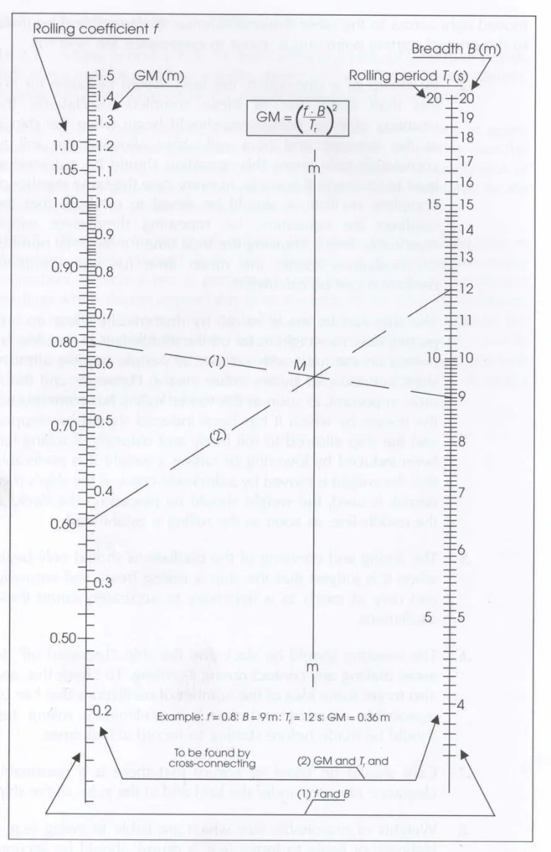
Fig.1
12.2Recommendations on procedures for the conduct of rolling tests
12.2.1 The rolling period required is the time for one complete oscillation of the vessel and to ensure the most accurate results in obtaining this value the following precautions should be observed.
.1The test should be conducted with the vessel in harbour, in smooth water with the minimum
interference from the wind and tide. .2Starting with the vessel at the extreme end of a roll to one side (say port) and the vessel about
to move towards the upright, one complete oscillation will have been made when the vessel has moved right across to the other extreme side (i.e. starboard) and returned to the original starting point and is about to commence the next roll. .3By means of a stop-watch, the time should be taken for not less than about five complete
oscillations. Counting of the oscillations should begin when the vessel is at the extreme end of a roll. After allowing the roll to completely fade away, this operation should be repeated at least twice more. If possible, in every case the same number of complete oscillations should be timed to establish that the readings are consistent, i.e. repeating themselves within reasonable limits. Knowing the total time for the total number of oscillations made, the mean time for one complete oscillation can be calculated. .4The vessel can be made to roll by rhythmically lifting up and putting down a weight as far off
the centreline as possible; by pulling on the mast with a rope; by people running athwartships in unison; or by any other means. However, and this is most important, as soon as this forced rolling has commenced, the means by which it has been induced should be stopped and the vessel allowed to roll freely and naturally. If rolling has been induced by lowering or raising a weight it is preferable that the weight is moved by a dockside crane. If the vessel’s own derrick is used, the weight should be placed on the deck, at the centreline, as soon as the rolling is established. .5The timing and counting of the oscillations should only begin when it is judged that the vessel
is rolling freely and naturally, and only as much as is necessary to accurately count these oscillations. .6The mooring should be slack and the vessel breasted off to avoid making any contact with the
wharf or any other structure during its rolling. To check this, and to get some idea of the number of oscillations that can be reasonably counted and timed, a preliminary rolling test should be made before starting to record actual times. .7Care should be taken to ensure that there is a reasonable clearance of water under the keel
and at the sides of the vessel. .8Weights of reasonable size which are liable to swing (e.g. a lifeboat), or liable to move (e.g. a
drum), should be secured against such movement. The free surface effects of slack tanks should be kept as small as is practicable during the test.
Pages 57–63 · View in original PDF